Tiberio Simonetti
| Inviato il: 06/10/2018 14:51:01
|
Descrizione vera e propria
Titolo : Sistema Coldairback per la produzione di energia elettrica da energia termica a temperatura ambiente.
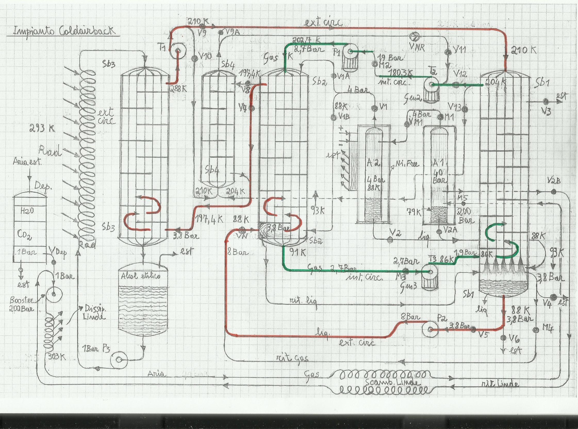
Il circuito interno indicato con int-circ � formato da : Sb2, T3, Sb1, T2, P1 al cui interno scorre sempre aria sotto forma di gas. La sua pressione varia continuamente tra 1,9 e 2,7 Bar. Il circuito esterno indicato con ext-circ � formato da : P2, Sb2, Sb4, Sb3, T1, Sb1 al cui interno scorre aria liquida, in vapore o in gas. La sua pressione � sempre costante con P = 3,8 Bar.
Motivi per la scelta del fluido vettore aria.
La scelta dell'aria apporta diversi vantaggi. E' un gas perfettamente ecologico, depurato da CO2 e da altri gas inquinanti, facilmente liquefabile da frigoriferi criogenici e non asfissiante in caso di perdite accidentali. Il liquido aria in fondo a Sb2 subisce una polverizzazione prodotta dalla valvola nebulizzatrice Vn, creando in ingresso allo scambiatore un volume liquido-vapore molto ampio. L'impianto � isolato (gli scambiatori hanno involucro esterno sottovuoto) e gli attriti dei vari dispositivi vengono riassorbiti dai serbatoi Sb1 e Sb2. L'efficienza per� � sempre inferiore a 1 in quanto non esistendo aria atmosferica in pressione, le perdite di fluido (inevitabili) devono essere reintegrate dai serbatoi di riserva A1-A2. Oltretutto, il prelievo di calore a temperatura ambiente in Sb3 � sempre accompagnato da energia elettrica consumata dalla pompa P3 che spinge alcol etilico nel radiatore Rad e preleva energia elettrica esterna. Si decide per tutte le turbine e la pompa idraulica P2 (escluso gli scambiatori e il compressore P1 ) un rendimento = 0,7 con pressioni d'aria pi� basse possibili per avere rendimenti accettabili anche con impianti di piccola potenza.Per queste infatti si considerano compressioni tra 1,9 e 2,7 ed espansioni isobare costantemente a 3,8 Bar.
Avviamento dell'impianto e periodo transitorio del circuito.
Viene prelevata elettricit� esterna per alimentare il frigo criogenico
(Ni-Free) e produrre aria liquida in A2. Per sicurezza � possibile
produrre aria liquida anche con il gruppo Linde, chiudendo M1 sul serbatoio A1 ed inviando aria proveniente dal dissipatore Linde. Questa espande in A1 con P = 1 Bar per poi raffreddare in scamb Linde in controfase se stessa, fino a completa liquefazione in A1 con T = 79 k. In seguito, vengono aperte per alcuni secondi le valvole V1, V3, V4 per espellere la normale aria presente in tutti i dispositivi, quindi il sistema invia aria liquida nel deposito Sb1. Le turbine ed il compressore partono con il gas che ancora esce dalle valvole V3 e V4, parzialmente chiuse (valvole a controllo elettrico) fino a che le temperature e le pressioni non si sono stabilizzate. Il sistema, con la lettura dei sensori, regola manometri, valvole e numero di giri delle pompe finch� non si raggiunge una certa stabilit�. La pompa P3 � ferma, e la turbina T1 � spinta dalla differenza di pressione tra il serbatoio A2 e la valvola V4 parzialmente chiusa.
Energia termica esterna in Sb3 e partenza del circuito interno.
l'Alcol Etilico ha caratteristiche di fluidit� fino a - 114 �C e quindi in grado di prelevare calore esterno e cederlo al fluido criogenico in Sb3 senza congelare.
Il circuito interno, partendo dallo scarico della turbina adiabatica T3 (T = 86 k) ha il compito di prelevare in Sb1 non solo energia termica al gas in ingesso su Sb1 (T = 210 k) ma anche la sua energia di liquefazione, il cui valore, se la sua pressione critica � di 3,8 Bar, vale 1140 Joul (questo valore verr� trovato con il grafico di compressibilit�).
La portata nel circuito interno � di 20 grammi / sec mentre la portata del circuito esterno vale 10 gr / sec. Il fluido in discesa in Sb1, per poter liquefare, deve raggiungere la sua temperatura critica che vale 93 k (P crit e T crit verranno trovati sul grafico di compressibilit�) come indicato nel disegno in basso su Sb1 e cedere energia pari a (la capacit� termica dell'aria vale 1 kj/kg) : (210 k - 88 k ) x 10 gr+1140 joul =2360 joul. L'altro gas (sempre aria con T = 86 k) in risalita con portata = 20 gr, deve prelevare : (2360 : 20 gr) =118 k +86 k (temp in uscita da T3) =204 k ( temp di uscita alta del circ int su Sb1). Questo valore � inferiore di 6 k rispetto alla temperatura in ingresso su Sb1 che vale come detto 210 k, quindi lo scambio diventa fattibile sia dal punto di vista fisico che meccanico. In sostanza, il gas in discesa su Sb1, entra nel deposito liquido gi� preparato anzitempo dal frigo criogenico e liquefa totalmente. Naturalmente � necessario calcolare le superfici esposte allo scambio ed i volumi, affinch� il gas abbia tempo e si verifichi una liquefazione totale (si far� un esempio su questo scambiatore).
Lavoro turbina T3
Sulla turbina adiabatica T3 � posto il manometro M3 tarato a 2,7 Bar, mentre il manometro M2 � davanti al compressore P1 e tarato a 1,9 Bar. T3 riceve aria a 2,7 Bar compressa da P1, ma raffreddata in Sb2 dal gas liquido che con T = 88 k in risalita, raffredda l'altro in discesa fino a T = 91 k. Il lavoro prodotto in T3 porta il gas in uscita a circa 86 k. Infatti si ha : 91 k x (( 1,9 Bar / 2,7 Bar) x 0,94 (Z) ) * 0,286 = 83,7 k (valore teorico) con un delta T = 91 k - 83,7 = 7,2 k x 0,7 (efficienza) = 5,06 k (delta T reale). Infine, questo � il valore che deve essere tolto a 91 k per avere : 91 k - 5 k = circa 86 k. Il lavoro positivo prodotto con l'espansione vale : 5 k x 20 gr = 100 joul (descriver� in seguito il valore di Z).
Lavoro pompa idraulica P2
Il delta T tra il valore 91 k in uscita in basso su Sb2 ed il valore 88 k del gas liquido in ingresso su Sb2 merita un approfondimento. La pompa idraulica P2 (molto piccola ) dovrebbe spingere a pressione costante il liquido da Sb1 a Sb2 ( 10 gr / sec ) perch� tra i due serbatoi � P=cost=3,8 Bar ed il suo lavoro dovrebbe essere nullo, ma prima che il fluido entri in Sb2 la valvola nebulizzatrice Vn polverizza il fluido aumentando la uperficie di scambio tra pareti dello scambiatore e fluido. Questa operazione comporta un prelievo in pi� di energia da parte della pompa P2 ma che non ha influenza sui valori termodinamici all'interno del circuito. In sostanza, lo sforzo della pompa e quindi il suo assorbimento elettrico esterno pu� valere al massimo (con P = 8 Bar) una potenza pari a : (0,01 kg x 8 Bar x 10 metri) / 0,7 x 102= 11,2 joul. Questo valore compensa grosso modo l'energia che agisce con la nebulizzazione mentre le perdite reali della pompa potrebbero essere al massimo uguali a 2-3 joul ed essere caricate nel sistema. La pompa inoltre regola in Sb2 anche la portata e quindi la pressione del circuito esterno su tutti i vari dispositivi. La stessa cosa vale per P1 che opera nel circuito interno. La portata interna infatti dipende da questo dispositivo che accelera o diminuisce in velocit� a seconda dei casi regolando gas e pressione (ma solo qualche decimo di Bar) in Sb2. Per regolazioni pi� ampie, se necessario, possono intervenire i manometri ed il blocco A1-A2.
Lavoro turbina T2
L'uscita in alto su Sb1 come calcolato vale 204 k ed il gas con questo valore entra in turbina T2. L'espansione � a pressione costante con P = 1,9 Bar e regolata dal manometro M2. Questo valore di pressione � quello che entra nel compressore P1. Il lavoro isobaro prodotto da T2 vale : 2360 joul (questa � l'entalpia che il gas in risalita deve prelevare dall'altro in discesa) x 0,287 (cost per l'aria) x 0,7 (rend)=+ 474 joul , mentre la temperatura in uscita da T2 vale : Tutto il lavoro prodotto diviso la quantit� in grammi del gas, ed il risultato sottratto al valore di temperatura del fluido prima di entrare in turbina : 474 joul / 20 gr=23,7 k che sottratti a 204 k da il valore in uscita da T2 , ossia 204-23,7=180,3 k.
Compressione adiabatica del compressore P1.
Il gas con 180,3 k entra in P1 e viene compresso adiabaticamente da 1,9 a 2,7 Bar con un rendimento uguale a 0,85. Questa efficienza � ottenibile con pressioni molto basse in cui non ci sono trafilamenti di fluido e pochi attriti (compressore oil-free). L'aumento di temperatura con la compressione vale : 180,3 k x (2,7 / 1,9 ) *0,286 = 199,36 k con un delta T = 19,06 k che diviso per 0,85 = 22,42 k da un lavoro negativo di 22,42 x 20 gr = 448 joul. L'energia in pi� immessa dal compressore � rappresentata dall'incremento di temperatura di 22,42 k e caricata in ingresso allo scambiatore Sb2.
Scambi in Sb2
La T del fluido in uscita da P1 e in ingresso su Sb2 diventa : 180,3 + 22,4 = 202,7 k. In Sb2 inizia il raffreddamento fino a 91 k ed il fluido cede energia uguale a : (202,7 - 91 ) x 20 grammi = 2234 j. Il liquido in risalita ne preleva : 2234-1140 (entalpia evaporazione) : 10 gr = 109,4 k + 88 k (temp di partenza del liquido)=197,4 k valore inferiore di 5,3 k rispetto ai 202,7 in uscita da P1 per cui pu� essere accettato come temperatura del fluido in ingresso a Sb3. Sb4 � interdetto in quanto la valvola V8 � chiusa (descriver� in seguito lo scambiatore Sb4) ed il fluido passando attraverso la V7 si dirige verso Sb3.
Scambi in Sb3
L'uscita in basso su Sb2 vale come detto 91 k con P = 2,7 Bar , mentre in alto il gas in uscita da Sb2, entra in Sb3 passando sulla valvola V7, ed esce, dopo aver recuperato energia termica dal radiatore Rad. In questo circola Alcol Etilico liquido la cui temperatura vale circa 290 k. Il gas (proveniente da Sb2) invece entra in Sb3 con T = 197,4 k ed esce da Sb3 con un valore uguale a circa 288 k, poi entra in turbina T1 a pressione costante con P = 3,8 Bar. I valori di pressione vengono regolati (una sola volta) dal manometro M1 e dalla valvola V1 con il contenitore d'aria A1-A2 che entrano in azione solo se la pressione interna scende sotto ad un certo valore. Se invece i valori di pressione dovessero aumentare accidentalmente, allora vengono aperte le valvole di sicurezza V3 e V4. Tornando ancora allo scambiatore Sb3, secondo i valori di temperatura voluti in progetto, l'alcol etilico cede energia pari a : (288 k - 197,4 k) x 10 gr / sec = 906 joul termici
Lavoro turbina T1
La turbina T1 � soggetta ad una doppia sollecitazione. Da una parte (in Sb2) il gas liquido deve espandere (con espansione = cost = 3,8 Bar) e quindi tende ad accelerare, mentre dall'altra (in Sb1) lo stesso gas tende a liquefare diminuendo velocemente il suo volume. In sostanza, in Sb2, il gas spinge verso T1, mentre in Sb1 il gas aspira da T1. Il lavoro prodotto allora � doppio rispetto a quello se ci fosse un solo scambiatore : Lavoro T1 = ( 288 k -93 k ) x 10 grammi x 0,287 (costante aria ) x 2 (Sb2 ed Sb1 ) = 1119 joul x 0,7 (rend) = 783 joul. La sua temperatura di uscita ha un valore di : 783 j / 10 gr = 78,3 k e da qu� si ottiene la T in uscita da T1 : 288 k - 78 = circa 210 k che � poi il valore di ingresso del gas in Sb1.
Saldo energetico e primo principio termodinamico.
Finita la descrizione dell'intero ciclo � possibile adesso fare un calcolo del lavoro positivo prodotto :
+ L estratto = 783 j (L T1)+ 474 j (L T2) + 100 j (L T3) = 1357 joul; mentre l'energia immessa vale: Q immessa = 448 j (L P1) + 906 j (rad esterno)+3 j (L P2)=1357 joul. Netto = 1357-448-3 = 906 j meccanici che corrispondono all'energia termica prelevata in Sb3.
Il rendimento uguale a 1 � solo teorico perch� � stata consumata energia per comprimere in partenza aria nei serbatoi A1-A2 e al lavoro meccanico netto prodotto deve essere tolto ogni tanto quello necessario alla ricompressione. Con impianti di media potenza da 4-500 kw i rendimenti delle turbine centripete arrivano a circa 0,85-0,88 aumentando anche la potenza meccanica netta prodotta fino a circa 1,25 kjoul / 10 gr.
Confronto con il secondo principio termodinamico
Il secondo principio, fra i vari enunciati, fa anche riferimento all'impossibilit� che un qualsiasi sistema possa funzionare se ha una sola fonte di calore. In sostanza � necessario che una parte dell'energia prelevata dalla fonte di calore primaria debba essere espulsa verso l'esterno (ossia verso l'ambiente). Nel merito questo non � possibile in quanto le temperature di lavoro sono molto al di sotto della T ambiente. Esiste per� nell'impianto un pozzo di scarico dinamico in cui vengono scaricati gli attriti di tutti i dispositivi e che trasforma l'energia termica in avanzo (ossia gli attriti e tutte le perdite) in lavoro utile. Questo pozzo di scarico � il circuito interno. In esso infatti il gas criogenico in uscita dalla turbina T3, ed in risalita su Sb1, preleva nello scambio tutto il calore e l'energia di liquefazione dall'altro in discesa, per poi convertirla in lavoro utile prima in T2 e poi in T3 mantenendo costante ad ogni ciclo i valori di pressione e di temperatura.
In questo modo si � in perfetta sintonia anche con il secondo principio. L'entalpia di liquefazione invece ( 1140 j), prelevata in Sb1, � sempre la stessa e non viene trasformata in lavoro ma ceduta continuamente al fluido liquido in risalita su Sb2. Questo infatti ha necessit� di tornare nello stato di gas ed essendo liquido e pi� freddo (86-88 k) rispetto all'altro compresso (202,7 k), non pu� fare altro che recuperare energia termica ed energia di vaporizzazione che lui stesso ha ceduto anzitempo in Sb1. Nello scambio (in Sb2) supera la temperatura critica che con P = 3,8 Bar vale 93 kelvin e va su di nuovo sottoforma di gas aumentando di volume e portando energia termica esterna in turbina T1. La pompa P2 che preleva il liquido in Sb1, in teoria non farebbe nessuno lavoro, perch� riceve e spinge a pressione costante (P ing pompa = P ing Sb2 = 3,8 Bar), mentre il lavoro di polverizzazione sulla valvola Vn non influisce sull'equilibrio temodinamico.
Approfondimento sulla liquefazione dell'aria in Sb1.
Se si fa riferimento alla tabella delle caratteristiche fisiche dei gas criogenici si nota il comportamento dell'aria nella zona critica. Tra il punto di ebollizione e quello di rugiada c'� una differenza di 3 k. In Sb1 allora nel punto critico = 93 k con il solo prelievo dell'energia di liquefazione il fluido scende di 3 k portandosi a 90 k. Una volta liquido, continua a scambiare con l'altro che in ingresso ha sempre 86 k. Con una media ponderata il liquido dovrebbe scendere sotto al valore di 88 k : (86 k x 20 gr + 90 k x 10 gr) : 30 gr= 87,3 k. Questa differenza rende stabile l'intero processo perch� la tendenza � ad un graduale raffreddamento del fluido.
Stabilizzare la temperatura con il circuito di reazione Sb4.
Lo scambiatore Sb4 � posizionato nel disegno tra gli scambiatori Sb2 ed Sb3. Questo, se innescato con la valvola V8 (chiudendo tutta o parzialmente la V7), provoca una reazione negativa sul valore di temperatura in ingresso allo scambiatore Sb1, ( T = 210 k) ed entra in funzione solo se il valore 210 k tende ad aumentare. Con la chiusura della valvola V7 e aprendo la V8, il fluido anzich� transitare direttamente in Sb3 entra prima in Sb4 raffreddando l'altro (ma � sempre se stesso) che dalla turbina T1 entra in Sb4 e va su in uscita verso lo scambiatore Sb1 con T = 210 k. La media ponderata infatti da : (210 x 10 gr + 197,4 x 10 gr) : 20 gr = 203,7 k. Questo valore sostituirebbe lentamente l'altro, cercando di reagire ad un eventuale aumento di temperatura.
La stessa cosa � necessaria nel caso invece la T scenda sotto i 205 k. Il sistema interviene allora chiudendo V12 ed aprendo V11 e V13. Il valore 204 k in ingresso alla turbina T2 verrebbe spostato verso Sb4 facendolo scambiare con l'altro a 197,4. Il nuovo valore in ingresso su T2 porterebbe ad una diminuzione della T in ingresso su Sb2 facendo diminuire a sua volta il valore 197,4 k e cos� via fino a mantenere un delta T accettabile tra T ingresso Sb1 e T ingresso T2 ( con Sb4 in sostanza, � possibile controllare i valori di temperatura in ingresso ed in uscita su Sb1 alto).
Produzione ed estrazione di aria liquida
Volendo, una parte di energia elettrica prodotta pu� andare ad alimentare il frigo ad azoto (o il gruppo Linde) per produrre aria liquida in avanzo e scaricarla aprendo la valvola V6 sul deposito in Sb1. Naturalmente � possibile ottenere risultati simili pure con gas diversi dall'aria e quindi l'idea rivendica anche l'utilizzo di un'altro tipo di gas utile come gas vettore per produrre sia energia elettrica che gas liquidi.
Manometri elettrici M1-M5 e valvole V1-V13.
Questi dispositivi devono essere a variazione di pressione e di portata (con motori elettrici). IL sistema dopo aver prodotto aria liquida, apre la valvola V2 ed invia il fluido in fondo a Sb1. Per l'inserimento del liquido nebulizzato in Sb2 viene aperta la valvola V5 dopo di che la pompa P2 inizia ad inviare il liquido verso Sb2. Nel frattempo il serbatoio A2 invia gas in pressione in Sb1- Sb2 e il compressore P1 comprime gas in Sb2. I manometri criogenici si posizionano con comando a motore al valore di pressione voluto dall'algoritmo che legge i valori dai sensori posizionati nei vari punti del circuito. Se non dovessero essere conformi a quanto stabilito, il sistema interviene sui vari dispositivi stabilizzando temperature e pressioni.
Calcolo dell'entalpia di liquefazione con Grafico generalizzato.
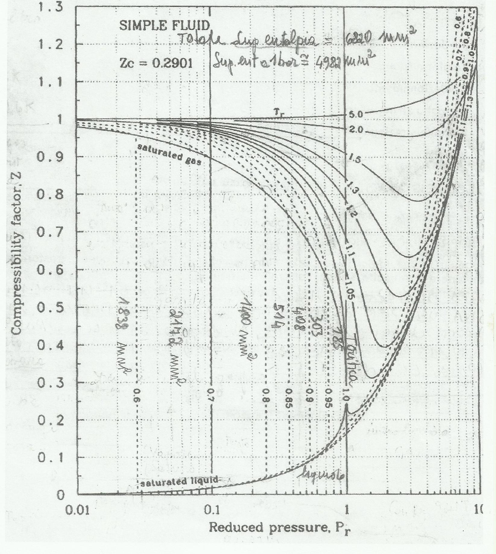
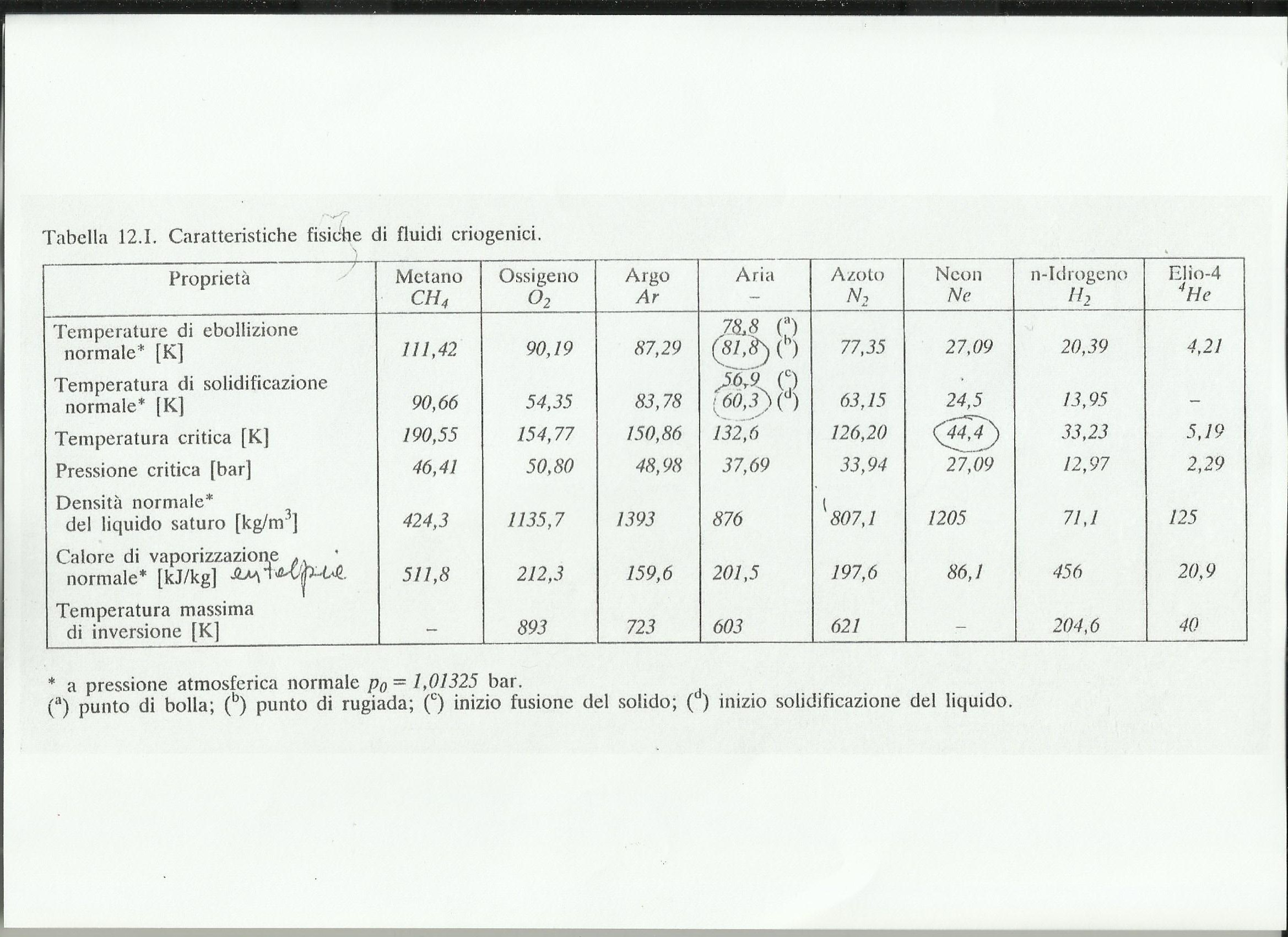
Leggendo la tabella delle caratteristiche fisiche dei fluidi criogenici , in riferimento all'aria , vengono acquisiti subito i valori di T crit, di P crit e tutti gli altri. Con questi � possibile interpretare il grafico di compressibilit�. In riferimento all'aria, si ha P rid = 0,1 quando la sua pressione reale viene divisa per la sua pressione critica : P rid = 3,8 Bar / 37,7 Bar = 0,1. Allo stesso modo si calcola la T rid che vale: 93 k / 132,6 k = 0,7. Nel grafico di compressibilit� si notano 3 zone, quella liquida, quella liquido-vapore e quella del gas. La zona di vapore parte con T crit = 0,6 quando la pressione vale 1 Bar e la temperatura del fluido vale appunto 0,6 x 132,6 = 79,6 kelvin. Nel merito con T crit = 93 k � appunto : 0,7 x 132,6 = 93 k ed in corrispondenza sulle pressioni ridotte c'� il valore 0,1 che moltiplicato per 37,7 da circa 3,8 Bar. Tutta la zona di vapore (guardando sempre il grafico) � divisa in settori la cui area in millimetri vale : 2172 + 1400 + 514 + 408 + 303 + 185 = 4982 mm quadri (il grafico � ingrandito ma applicando lo stesso sistema alla superficie che si ha a disposizione si ottengono gli stessi risultati). Partendo a sommare le aree dal valore T rid = 0,7 fino ad arrivare a T rid = 1 si trova un valore uguale a 2810 mm quadri , equivalenti all'entalpia compresa tra 0,7 ed 1. Ora conoscendo l'entalpia di liquefazione dell'aria ad 1 Bar di pressione (201,5 kj / kg e 2,015 kj / 10 gr ) con Trid = 0,7 � possibile trovare quella compresa tra 0,7 ed 1 che vale : (2810 / 4982) x 2,015 kj / gr = 1136 joul arrotondati a 1140 joul.
Individuazione del fattore di compressibilit� Z sul grafico.
L'unico dispositivo su cui � necessario calcolare il valore di Z � la turbina adiabatica T3 ( le altre espansioni e compressioni hanno tutte un valore di Z tra 0,99 e 1 ). Su questa infatti confluisce il fluido con T = 91 k e pressioni tra 2,7 e 1,9 Bar. Con 91 k si ha T rid = 91 / 132,6 = 0,686 mentre con 2,3 Bar (P media tra 2,7 e 1,9) si ha P rid = 2,3 / 37,7 = 0,061. Riportando ora i due valori sul grafico si trover� un punto di incontro che da un valore di Z uguale a circa 0,94. Questo coefficiente (Z) rappresenta l'influenza dell'energia potenziale sull'energia cinetica dei gas.
Criteri di scelta per gli scambiatori di calore Sb1-Sb4
Lo scambio energetico in Sb1 per liquefare 10 grammi d'aria al secondo tra T ingresso = 210 k e T uscita liquida = 88 k vale come gi� calcolato 2360 joul. Questo � il valore energetico che deve essere trasmesso dall'aria in pressione all'altro fluido criogenico (pure aria) a pi� bassa temperatura. I volumi dei rispettivi fluidi sono esigui. Ad esempio i 10 gr d'aria che devono essere liquefatti in Sb1 corrispondono a circa : [10 gr : 1,63 (peso spec a 210 k)] : 3,8 (press) = 1,6 lt , mentre un attimo prima della liquefazione hanno volume di : [10gr : 3,85 (peso spec a 93 k)] : 3,8 (press) = 0,68 lt. Lo stesso calcolo pu� essere fatto per l'altro fluido del circuito interno che con 20 grammi vale 6 lt a 204 k e 2,7 lt a 88 k. I volumi degli scambiatori, affinch� i fluidi rimangano almeno per 10 secondi al loro interno, dovanno avere volumi 10 volte pi� grandi prima che essi possano uscire definitivamente. Quindi uno scambiatore, dovr� avere grosso modo un volume uguale a circa 60 litri. Per poter occupare meno spazio possibile ed essere sicuri che con un delta minimo di 3-7 kelvin lo scambio e la liquefazione dell'aria siano assicurati, penso sia conveniente scegliere uno scambiatore a piastre del tipo ispezionabile. I costruttori garantiscono buona funzionalit� anche con differenze di temperatura di un solo kelvin. I cambiamenti di fase presenti nel circuito esterno dovrebbero tra l'altro aumentare molto il cefficiente di scambio, ridimensionandone i volumi.
Perdite di carico nell'impianto
Costruite le condotte e gli scambiatori secondo quanto gi� detto in merito al calcolo dei volumi, le perdite di carico diventano irrilevanti. Anche i manometri e le valvole per� devono essere un p� maggiorati.
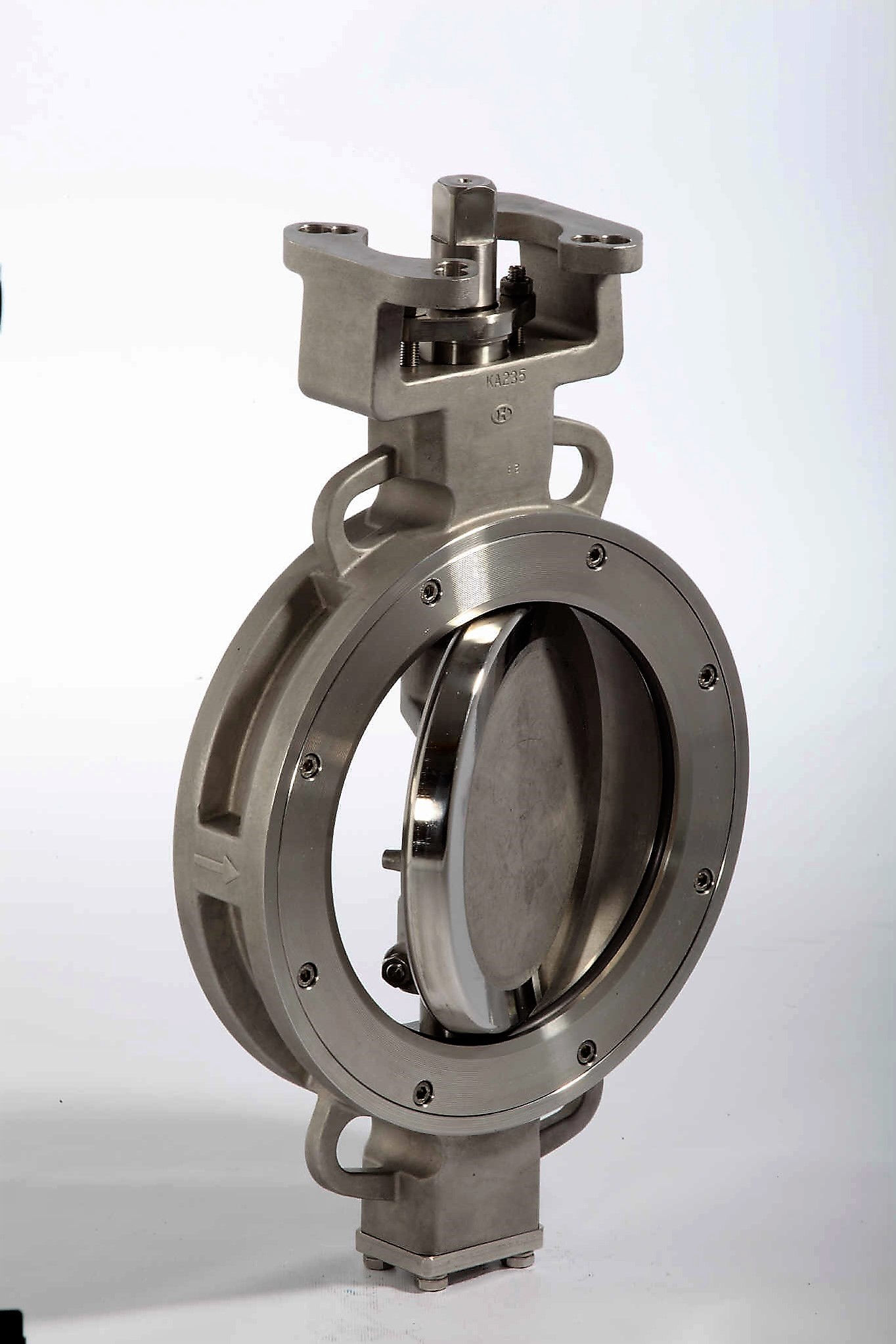
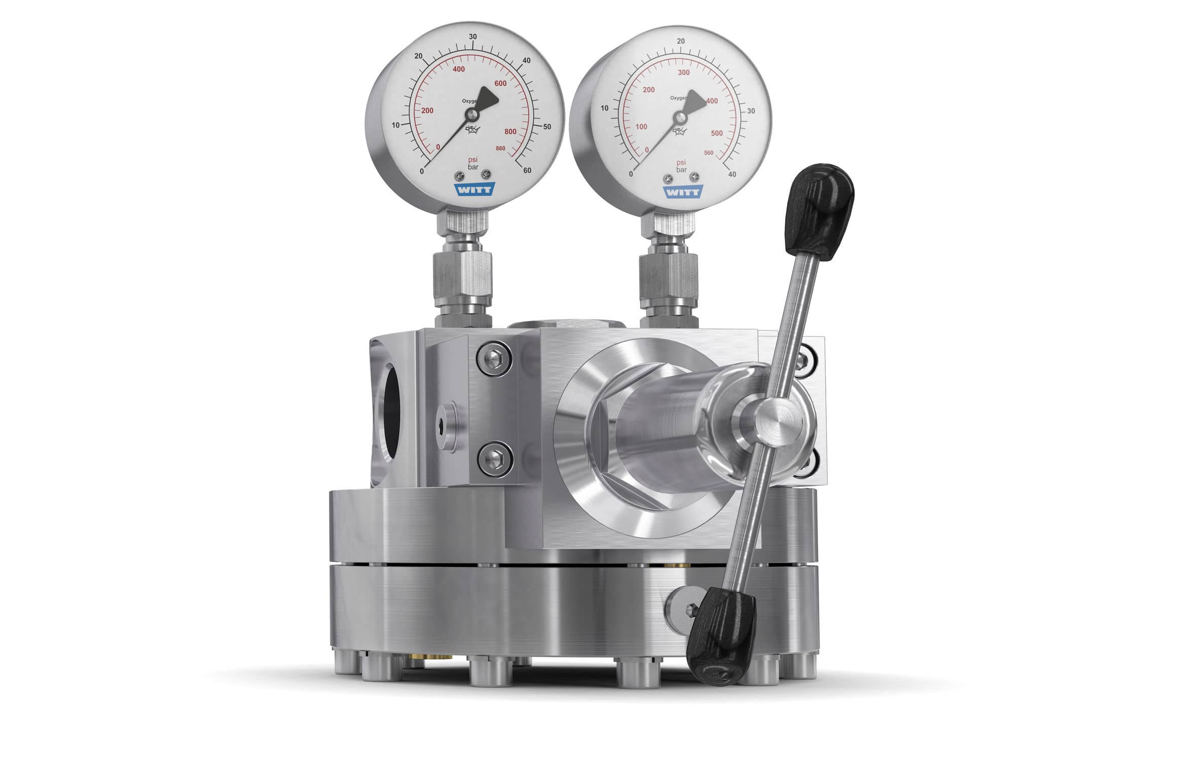
Depliant turbina, riduttori di pressione, valvole e booster
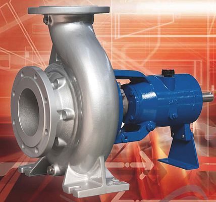
Le macchine sono tutte in acciaio austenitico, come d'altronde anche le condotte (AISI 304, 304L, 316). L'inox � necessario se si hanno fluidi criogenici. La turbina centripeta, ad esempio, ha rendimenti sempre abbastanza alti anche quando la sua grandezza � esigua con potenze che partono da qualche kw fino a alcune migliaia di kw.
Produzione di Idrogeno e scissione della CO2
Volendo, una piccola parte di elettricit� pu� essere utilizzata per scindere la molecola CO2 e depurare l'ambiente. Ugualmente � possibile produrre Idrogeno ed ossigeno da elettrolisi per poi riutilizzarli come carburanti per autotrazione o altro.
Originalit�, fattibilit� ed interesse a costruire
Per concludere, evidenzio i punti principali sui quali si basa la domanda di brevetto : E' originale, in quanto non risulta in funzione (per quanto mi � stato possibile vedere sulla rete), ne in Italia ne all'estero un impianto che produca energia nel modo in cui l'idea � stata sviluppata. E' fattibile sia dal punto di vista fisico che meccanico, con prodotti all'avanguardia presenti sul mercato a prezzi accettabili. E' interessante economicamente perch� produce energia a basso prezzo e gas liquidi anche per scopi diversi da quelli strettamente necessari all'impianto stesso.
In fede Tiberio Simonetti
Rivendicazioni
1- L'impianto � caratterizzato dal fatto che prelevi energia termica a temperatura ambiente, la ceda al gas criogenico interno ( in questo caso aria, ma � possibile usare anche un' altro gas utile allo scopo) e la trasformi in energia meccanica e quindi elettrica.
2- L'impianto � caratterizzato dal fatto che depuri aria atmosferica con la "cattura" della CO2 e la depositi nel depuratore per essere scissa poi in Carbonio ed Ossigeno.
3- L'impianto � caratterizzato dal fatto che pu� produrre ed estrarre aria liquida (e se necessario pure altri gas liquidi) anche per scopi diversi da quelli descritti nell'impianto.
In fede : Tiberio Simonetti
Claims
1- The system is characterized by the fact that it takes thermal energy at room temperature, gives it to the internal cryogenic gas (in this case air, but it is also possible to use another gas useful for the purpose) and transform it into mechanical energy and then electricity.
��
� 2- The plant is characterized by the fact that it purifies atmospheric air with the "capture" of the CO2 and the deposits in the purifier to be then divided into Carbon and Oxygen.
��
3- The plant is characterized in that it can produce and extract liquid air (and if necessary also other liquid gases) also for purposes other than those described in the plant.
In faith: Tiberio Simonetti
Summary
Title: Coldairback system for the production of electricity from thermal energy at room temperature.
I had applied in 2007 based on this idea and obtained the patent n � 0001383773. 12 years have passed and the technologies have changed to a point that has convinced me to change the old project. So, I also simplified the circuits, I used air instead of the neon (cost of the Neon 6000 euro / kg) and used much lower pressures. The old patent was very complex, while this demand demonstrates constructive simplicity, enormous advantages for costs, assembly times and occupied volumes. The name Coldairback is almost an acronym and summarizes the idea quite simply.
The carrier is liquid air at about 86-88 K and 3.8 Bar of pressure. Using ambient thermal energy it is returned to the gaseous state making it expand on three turbines assisted by a compressor and a hydraulic pump. At the beginning it is necessary to supply electricity, after which the whole system is self-sustaining. This is the list of the most important devices:
�
N � 4 exchangers indicated with Sb1-Sb4 with Rad radiator
N � 3 turbines, T1-T3 with the relative Gen1-Gen3 electric generators;
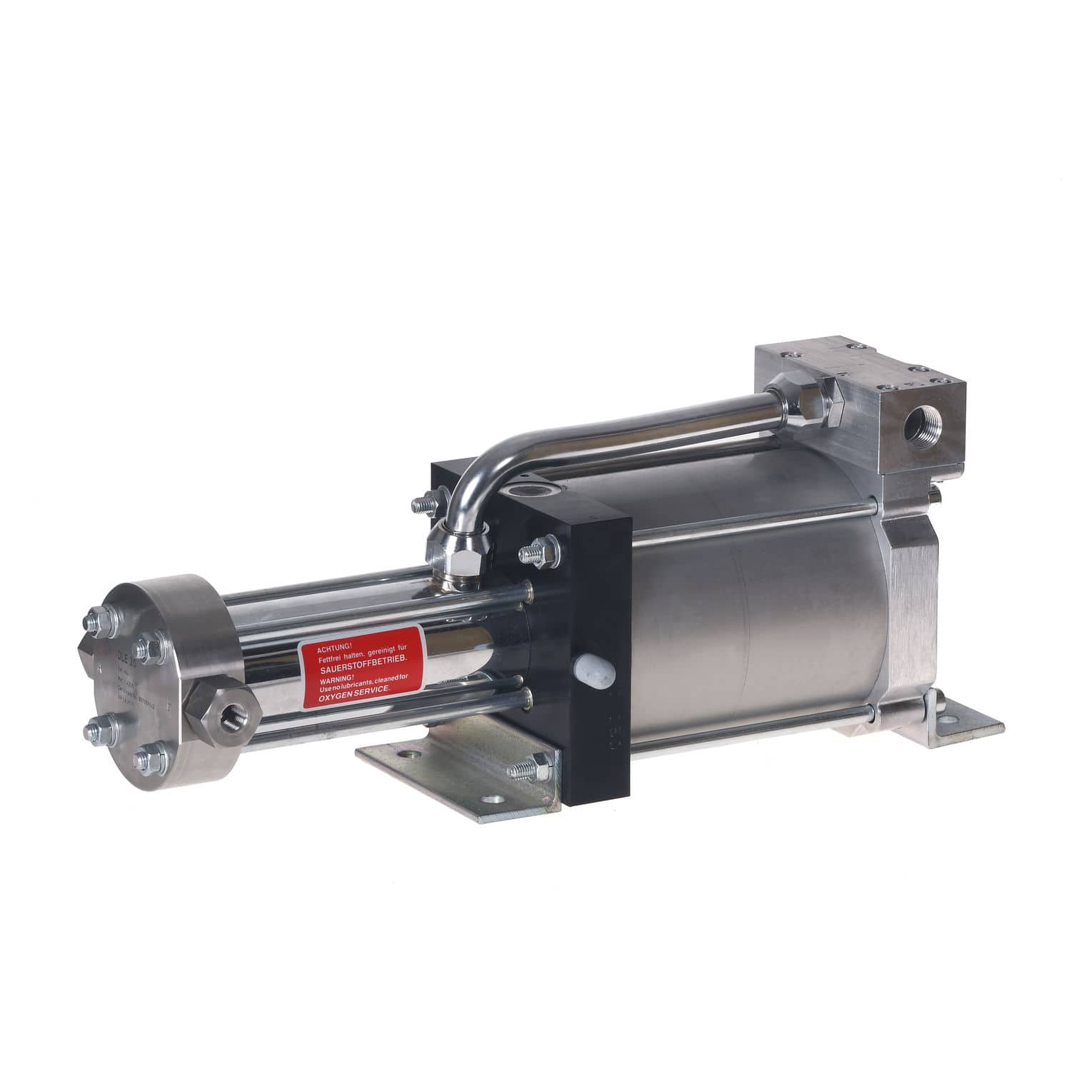
No. 1 compressor indicated with P1 and a 200 Bar Booster;
N � 1 purifier indicated with Dep; 2 hydraulic pumps indicated with P2-P3; 5 pressure gauges indicated with M1-M5; 13 V1-V13 valves + 1 VN nebulizer valve + 1 VNR non-return valve; 1 tank containing denatured ethyl alcohol;
1 cryogenic refrigerator + 2 A1-A2 air tanks.
Air flow rate for the internal circuit int-cric = 20 grams / sec;
Air flow rate for the external circuit ext-circ 10 grams / sec.
Mechanical power developed 906 watts / 10 grams.
�������������������������������������������������
Real description
Title: Coldairback system for the production of electricity from thermal energy at room temperature.
The internal circuit indicated with int-circ is formed by: Sb2, T3, Sb1, T2, P1 inside which air always flows in the form of gas. Its pressure varies continuously between 1.9 and 2.7 Bar. The external circuit indicated with ext-circ is formed by: P2, Sb2, Sb4, Sb3, T1, Sb1 in which liquid air flows, in steam or in gas . Its pressure is always constant with P = 3.8 Bar.
Reasons for choosing the air carrier fluid.
The choice of air brings several advantages. It is a perfectly ecological gas, purified of CO2 and other polluting gases, easily liquefied by cryogenic and non-suffocating refrigerators in case of accidental losses. The air liquid at the end of Sb2 undergoes a pulverization produced by the Vn atomizing valve, creating a very large liquid-vapor volume at the inlet of the exchanger. The plant is isolated (the exchangers have external vacuum envelope) and the frictions of the various devices are reabsorbed by the tanks Sb1 and Sb2. However, efficiency is always lower than 1 because there is no atmospheric air under pressure, the fluid losses (unavoidable) must be reintegrated from the reserve tanks A1-A2. Moreover, the heat transfer at room temperature in Sb3 is always accompanied by electricity consumed by the P3 pump which pushes ethyl alcohol into the Rad radiator and picks up external electrical energy. It is decided for all the turbines and the P2 hydraulic pump (excluding the exchangers and the P1 compressor) a yield = 0.7 with the lowest possible air pressures to have acceptable yields even with small power plants. For these are considered compressions between 1.9 and 2.7 and constant isobar expansions at 3.8 Bar.
System start-up and transitory period of the circuit.
External electricity is taken to supply the cryogenic fridge
(Ni-Free) and produce liquid air in A2. For security it is possible
produce liquid air also with the Linde group, closing M1 on the tank A1 and sending air coming from the heatsink Linde. This expands in A1 with P = 1 Bar and then cooled in Linde exchange in reverse phase itself, until complete liquefaction in A1 with T = 79 k. Subsequently, the valves V1, V3, V4 are opened for a few seconds to expel the normal air present in all the devices, then the system sends liquid air into the Sb1 deposit. The turbines and the compressor start with the gas still coming out of the partially closed valves V3 and V4 (electrically controlled valves) until the temperatures and pressures have stabilized. The system, by reading the sensors, regulates pressure gauges, valves and number of revolutions of the pumps until a certain stability is achieved. Pump P3 is stationary, and turbine T1 is driven by the pressure difference between tank A2 and the partially closed valve V4.
External thermal energy in Sb3 and departure of the internal circuit.
the ethyl alcohol has fluidity characteristics up to - 114 � C and therefore able to take external heat and transfer it to the cryogenic fluid in Sb3 without freezing. The internal circuit, starting from the discharge of the adiabatic turbine T3 (T = 86 k), has the task of collecting in Sb1 not only thermal energy to the gas in input on Sb1 (T = 210 k) but also its liquefaction energy, whose value, if its critical pressure is 3.8 Bar, it is 1140 Joul (this value will be found with the compressibility graph).
The flow rate in the internal circuit is 20 grams / sec while the external circuit flow rate is 10 gr / sec. The fluid descending in Sb1, in order to liquefy, must reach its critical temperature which is 93 k (P crit and T crit will be found on the compressibility graph) as indicated in the drawing below on Sb1 and yield energy equal to (the capacity air temperature is 1 kj / kg): (210 k - 88 k) x 10 g + 1140 joul = 2360 joul. The other gas (always air) in ascent with flow = 20 gr, must pick up: (2360: 20 gr) = 118 k) +86 k (starting temperature at the output from T3) = 204 k (output temp of the circ int on Sb1). This value is less than 6 k with respect to the input temperature at Sb1 which is the same as 210 k, so the exchange becomes feasible from both a physical and a mechanical point of view. Basically, the gas downhill on Sb1 enters the liquid deposit already prepared ahead of time from the cryogenic fridge and liquefies totally. Of course it is necessary to calculate the surfaces exposed to the exchange and the volumes, so that the gas has time and a total liquefaction occurs (an example will be given on this exchanger).
Work T3 turbine
On the adiabatic turbine T3 is placed the M3 pressure gauge calibrated at 2.7 Bar, while the M2 pressure gauge is in front of the P1 compressor and calibrated at 1.9 Bar. T3 receives air at 2.7 Bar compressed by P1, but cooled in Sb2 by liquid gas that with T = 88 k in ascent, cools the other in descent up to T = 91 k. The work produced in T3 brings the outgoing gas to about 86 k. In fact we have: 91 kx (1.9 Bar / 2.7 Bar x 0.94 (Z)) * 0.286 = 83.7 k (theoretical value) with a delta T = 91 k - 83.7 = 7.2 kx 0.7 (efficiency) = 5.06 k (real delta T). Finally, this is the value that must be removed at 91 k to have: 91 k - 5 k = about 86 k. The positive work produced by the expansion is: 5 k x 20 g = 100 joules (I will describe the value of Z later).
Work hydraulic pump P2
The delta T between the value 91 k in output at the bottom on Sb2 and the value 88 k of the liquid gas inlet on Sb2 deserves further study. The hydraulic pump P2 (very small) should push the liquid from Sb1 to Sb2 (10 gr / sec) at constant pressure because between the two tanks it is P = cost = 3.8 Bar and its work should be zero, but before that the fluid enters into Sb2 the nebulizing valve Vn pulverizes the fluid, increasing the exchange surface between the exchanger and fluid walls. This operation involves a more energy pre-load from the P2 pump but that does not influence the thermodynamic values inside the circuit. In essence, the stress of the pump and therefore its external electrical absorption can be worth at most (with P = 8 Bar) a power equal to: (0.01 kg x 8 Bar x 10 meters) / 0.7 x 102 = 11 , 2 joul. This value roughly compensates for the energy that acts with the atomization while the losses could be estimated in 2-3 joules and be loaded into the system. The pump also regulates in Sb2 the flow rate and therefore the pressure of the external circuit on all the various devices. The same is true for P1 operating in the internal circuit. In fact, the internal flow depends on this device which accelerates or decreases in speed according to the case by regulating gas and pressure in Sb2. For larger adjustments, if necessary, the pressure gauges and block A1-A2 can intervene.
Work T2 turbine
The top output on Sb1 as calculated is worth 204 k and the gas with this value enters turbine T2. The expansion is at constant pressure with P = 1.9 Bar and regulated by the M2 pressure gauge. This pressure value is the one that enters the compressor P1. The isobaric work produced by T2 is worth: 2360 joul (this is the enthalpy that the rising gas must take from the other downhill) x 0.287 (cost for air) x 0.7 (yield) = + 474 joul, while the temperature exiting from T2 applies: All the work produced divided by the quantity in grams of the gas, and this subtracted from the temperature value of the fluid before entering the turbine: 474 joul / 20 gr = 23.7 k which subtracted from 204 k gives the output value from T2, i.e. 204-23.7 = 180.3 k.
Adiabatic compression of the P1 compressor.
The gas with 180.3 k enters P1 and is compressed adiabatically from 1.9 to 2.7 Bar with a yield equal to 0.85. This efficiency can be obtained with very low pressures in which there are no fluid leaks and few frictions (oil-free type). The increase in temperature with compression is: 180.3 kx (2.7 / 1.9) * 0.286 = 199.36 k with a delta T = 19.06 k which divided by 0.85 = 22.42 k from a negative work of 22.42 x 20 gr = 448 joul. The extra energy input from the compressor is represented by the temperature increase of 22.42 k and charged to the Sb2 exchanger.
Exchanges in Sb2
The T of the fluid leaving P1 and entering Sb2 becomes: 180.3 + 22.4 = 202.7 k. In Sb2 the cooling starts up to 91 k and the fluid transfers energy equal to: (202.7 - 91) x 20 grams = 2234 j. The rising liquid draws: 2234-1140 (enthalpy evaporation): 10 gr = 109.4 k + 88 k (liquid starting point) = 197.4 k lower value of 5.3 k compared to 202.7 in output from P1 for which it can be accepted as the temperature of the fluid inlet to Sb3. Sb4 is inhibited because the valve V8 is closed (I will describe the exchanger Sb4 later) and the fluid passing through the V7 goes towards Sb3.
Exchanges in Sb3
The output at the bottom on Sb2 is the same as 91 k with P = 2.7 Bar, while at the top the gas leaving Sb2, enters Sb3 passing on valve V7, and exits, after recovering thermal energy from the Rad radiator. In this circulates liquid ethyl alcohol whose temperature is worth about 290 k. The gas (coming from Sb2) instead enters about 288 k, then enters the turbine T1 at constant pressure with P = 3.8 Bar. pressure are regulated by the M1 pressure gauge and by the V1 valve with the A1-A2 air that come into action each time the internal pressure drops below a certain value. If the pressure values should increase accidentally, then the safety valves V3 and V4 are opened. Returning again to the Sb3 exchanger, according to the temperature values desired in the project, the ethyl alcohol yields energy equal to: (288 k - 197.4 k) x 10 g / sec = 906 thermal joules
Work T1 turbine
The T1 turbine is subjected to a double stress. On the one hand (in Sb2) the liquid gas must expand (with expansion = cost = 3.8 Bar) and therefore tends to increase in volume, while on the other (in Sb1) the gas itself tends to liquefy, rapidly reducing its volume. . Basically, in Sb2, the gas pushes towards T1, while in Sb1 the gas aspires from T1. The work produced then is double compared to that if there was only one exchanger: Work T1 = (288 k -93 k) x 10 grams x 0.287 (air constant) x 2 (Sb2 and Sb1) = 1119 joul x 0.7 ( rend) = 783 joul. Its outlet temperature has a value of: 783 j / 10 gr = 78.3 k and from here it is obtained 288 k - 78 = about 210 k which is then the value of gas inlet in Sb1.
Energy balance and first thermodynamic principle.
�Once the description of the whole cycle is over, it is now possible to calculate the positive work produced:
+ L extract = 783 j (L T1) + 474 j (L T2) + 100 j (L T3) = 1357 joul; while the energy input is valid:
Q entered = 448 j (L P1) + 906 j (external rad) +3 j (L P2) = 1357 joul. Net = 1357-448-3 = 906 mechanical j that correspond to the thermal energy taken in Sb3.
The efficiency equal to 1 is only theoretical because energy has been consumed to compress air in the A1-A2 tanks and the mechanical work produced must be removed for compression. With medium power plants of 4-500 kw the yields of centripetal turbines reach about 0.85-0.88, increasing also the net mechanical power produced up to about 1.25 kjouls / 10 gr.
Comparison with the second thermodynamic principle
The second principle, among the various statements, also refers to the impossibility that any system can function if it has only one source of heat. Basically it is necessary that a part of the energy taken from the primary heat source should be expelled outwards (ie towards the environment). On the merits this is not possible because the working temperatures are far below the ambient T. However, there is a dynamic drain well in the plant where the frictions of all the devices are discharged and which transforms the thermal energy into surplus (ie frictions and losses) into useful work. This drain well is the internal circuit. In fact, in fact the cryogenic gas leaving the turbine T3, and rising up Sb1, takes in the exchange all the heat and liquefaction energy from the other downhill, and then convert it into useful work first in T2 and then in T3 maintaining constant pressure and temperature values.
In this way you are perfectly in tune with the second principle. The liquefaction enthalpy instead (1140 j), taken in Sb1, is always the same and is not transformed into work but continuously transferred to the liquid fluid rising on Sb2. This fact needs to return to the state of gas and being liquid and colder (86-88 k) than the other compressed (202.7 k), can not help but recover thermal energy and vaporization energy that he himself has sold prematurely in Sb1. In the exchange (in Sb2) it exceeds the critical temperature which with P = 3.8 Bar is worth 93 kelvin and goes up again in the form of gas increasing in volume and bringing energy into turbine T1. The P2 pump that takes the liquid in Sb1, in theory, would not do any work, because it receives and pushes at constant pressure (P ing pump = P ing Sb2 = 3.8 Bar), while the pulverization work on the valve Vn does not affect the temodynamic balance.
Deepening on the liquefaction of air in Sb1.
If we refer to the table of physical characteristics of cryogenic gases, we note the behavior of the air in the critical area. Between the boiling point and the dew point there is a difference of 3 k. In Sb1 then at the critical point = 93 k with the only withdrawal of the liquefaction energy the fluid falls by 3 k to 90 k. Once liquid, it continues to exchange with the other that in input it always has 86 k. With a weighted average the liquid should fall below the value of 88 k: (86 k x 20 g + 90 k x 10 g): 30 g = 87.3 k. This difference stabilizes the whole process because the tendency is to gradually cool the fluid.
Stabilize the temperature with the Sb4 reaction circuit.
The exchanger Sb4 is positioned in the drawing between the exchangers Sb2 and Sb3. This, if triggered with the V8 valve (closing all or part of the V7), causes a negative reaction on the temperature value at the inlet to the exchanger Sb1, (T = 210 k) and goes into operation only if the value 210 k tends to increase . By closing the V7 valve and opening the V8, the fluid instead of passing directly into Sb3 first enters Sb4 cooling the other (but it is always itself) that from the turbine T1 enters into Sb4 and goes up to the outlet towards the exchanger Sb1 with T = 210 k. The weighted average in fact from: (210 x 10 gr + 197.4 x 10 gr): 20 gr = 203.7 k. This value would slowly replace the other, trying to react to a possible increase in temperature.
The same thing is necessary in the case instead the T falls below 205 k. The system then intervenes by closing V12 and opening V11 and V13. The value 204 k entering the turbine T2 would be moved towards Sb4 making it exchange with the other at 197.4. The new input value on T2 would lead to a decrease of the input T on Sb2 decreasing in turn the value 197.4 ke and so on until maintaining an acceptable delta T between T input Sb1 and T input T2 (with Sb4 in essence , it is possible to increase this difference as much as desired but to the detriment of a lower external heat draw.This entails a general decrease in the temperature values both in Sb1 and in Sb2 but also a decrease in the mechanical energy produced). With ambient below 0 � C it is also necessary to increase the flow rate in the internal circuit between 21 and 24 grams / sec and a water deposit with anti-freeze would be very suitable for supplying energy from the outside.
Production and extraction of liquid air
If desired, a portion of the electricity produced can feed the nitrogen fridge (or the Linde group) to produce surplus liquid air and discharge it by opening the valve V6 on the deposit in Sb1. Naturally, it is possible to obtain similar results even with gases other than air and therefore the idea also claims the use of another type of gas useful as carrier gas.
�
M1-M5 electric pressure gauges and V1-V13 valves.
These devices must be pressure and flow variation (with electric motors). After having produced liquid air, the system opens the valve V2 and sends the fluid to the bottom of Sb1. For the insertion of the nebulized liquid in Sb2 the valve V5 is opened, after which the pump P2 starts to send the liquid towards Sb2. Meanwhile, tank A2 sends pressurized gas into Sb1- Sb2 and compressor P1 compresses gas into Sb2. The cryogenic manometers are positioned with a motor drive at the pressure value desired by the algorithm that reads the values from the sensors positioned at the various points of the circuit. If they do not comply with the provisions, the system intervenes on the various devices, stabilizing temperatures and pressures.
Calculation of the liquefaction enthalpy with generalized graph.
Reading the table of the physical characteristics of cryogenic fluids, with reference to the air, the values of T crit, P crit and all the others are immediately acquired. With these it is possible to interpret the compressibility graph. With reference to air, P = 0.1 = 0.1 when its actual pressure is divided by its critical pressure: P = 3.8 = Bar / 37.7 Bar = 0.1. In the same way we calculate the T rid that is worth: 93 k / 132.6 k = 0.7. In the compressibility graph, 3 zones are noted, liquid, liquid-vapor and gas. The steam zone starts with T crit = 0.6 when the pressure is 1 Bar and the fluid temperature is just 0.6 x 132.6 = 79.6 kelvin. On the merit with T crit = 93 k is precisely: 0.7 x 132.6 = 93 k and in correspondence on the reduced pressures there is the value 0.1 which multiplied by 37.7 from about 3.8 Bar. steam area (always looking at the chart) is divided into sectors whose area in millimeters is worth: 2172 + 1400 + 514 + 408 + 303 + 185 = 4982 square mm (the graph is enlarged but applying the same system to the surface that you have the same results are obtained). Starting to sum the areas from the value T rid = 0.7 until you get to T rid = 1 you find a value equal to 2810 square mm, equivalent to the enthalpy between 0.7 and 1. Now knowing the liquefaction enthalpy of air at 1 Bar of pressure (201.5 kj / kg and 2.015 kj / 10 gr) with Trid = 0.7 it is possible to find the one between 0.7 and 1 which is valid: (2810/4982) x 2.015 kj / gr = 1136 joul rounded up to 1140 joul.
Identification of the compressibility factor Z on the graph.
The only device on which it is necessary to calculate the value of Z is the adiabatic turbine T3 (the other expansions and compressions all have a value of Z between 0.99 and 1). On this in fact flows the fluid with T = 91 ke and pressures between 2.7 and 1.9 Bar. With 91 k we have T rid = 91 / 132.6 = 0.686 while with 2.3 Bar (average P between 2.7 and 1.9) we have P rid = 2.3 / 37.7 = 0.061. If we now report the two values on the graph, we will find a meeting point that gives a value of Z equal to about 0.94. This coefficient (Z) represents the influence of potential energy on the kinetic energy of gases.
Selection criteria for Sb1-Sb4 heat exchangers
The energy exchange in Sb1 to liquefy 10 grams of air per second between T input = 210 k and T liquid output = 88 k counts as already calculated 2360 joules. This is the energy value that must be transmitted from the air under pressure to the other cryogenic fluid (air) at a lower temperature. The volumes of the respective fluids are small. For example, the 10 grams of air that must be liquefied in Sb1 correspond to approximately: [10 gr: 1.63 (spec weight to 210 k)]: 3.8 (press) = 1.6 lt, while a moment before of liquefaction have volume of: [10gr: 3.85 (spec weight to 93 k)]: 3.8 (press) = 0.68 lt. The same calculation can be made for the other fluid of the internal circuit which with 20 grams is worth 6 liters at 204 k and 2.7 liters at 88 k. The volumes of the exchangers, so that the fluids remain at least 10 seconds inside them, must have 10 times larger volumes before they can go out permanently. So an exchanger, must have roughly a volume equal to about 60 liters. In order to take up as little space as possible and be sure that with a minimum delta of 3 kelvin the exchange and the liquefaction of the air are ensured, I think it is convenient to choose an inspectable type plate exchanger. The continuous changes in the state of the fluid deposit in the long run of the deposits that can be eliminated much better with an inspectable heat exchanger. The elements must all be in aluminum and the gaskets possibly in graphite. These lend themselves perfectly to the forming of the internal cavities and have no problems even at -200 � C. In any case, the manufacturers guarantee good functionality even with temperature differences of only one kelvin. The volumes must also take into account the continuous phase changes that occur in the external circuit.
Calculation of the volumes of the exchangers with medium-large powers
The project described is preparatory. The volumes occupied with respect to the produced power take up enough space and the average costs at kw el are inevitably higher than those of medium to large powers. The discourse changes when it is possible to build a medium-large plant. Since the technology offers steam turbines whose standard working pressures are worth 250 Bar and yields between 0.88 and 0.9, I do not think there may be problems if some of these should work for example at 40 Bar. The critical pressure of the in fact, when T = 132.6 kelvin is worth 37.7 Bar (see table) so if the circuit pressure should be 40 bar when the fluid in Sb1 cooling should fall below 132.6 k would have no problem liquefying, bringing directly from the state of gas to the liquid state by instantly bypassing the vapor state. The compressibility graph highlights this particularity, which with a P slightly higher than 1, falling below the critical T value = 132.6 k is jumped directly into the liquid state without yielding liquefaction enthalpy. This process brings two advantages on the volumes of the exchangers: Less exchange surface due to the lack of enthalpy and greater fluid density. Making a rough calculation, the first calculated 60-liter volume should be divided by about: (40: 3.8) x (2360: (2360-1140) = 20.3, so the volume in proportion would become 60: 20 = about 3 liters (and for 1kg of air 300 liters), among other things, the transmission coefficient for the increase in density of up to 10 times would be increased, of course this is not possible if you are dealing with plants of small size but for large plants the costs per kw could fall even below 2000 euro / kw el. With a maximum count if you want to produce 1250 kw el (average power) compared to 1.25 kw and as project the volumes of the exchangers should reach a maximum of: 60 liters x 1000 = 60 cubic meters: 20 = 3 cubic meters for each exchanger with a power output of 1.25 MW.The volume may be smaller if we consider the exchange rate and the status changes. The presented project therefore operates with low pressures because the high limit the yields with plants g instead, it is possible to work with bigger pressures (max 40 Bar) and with smaller volumes.
Losses of load in the system
If the pipelines and heat exchangers are built according to what has already been said regarding the calculation of the volumes, then the load losses are irrelevant. However, the pressure gauges and valves must also be somewhat larger.
Depliant turbine, pressure reducers, valves
The machines are all made of austenitic steel (AISI 304, 304L, 316). Stainless steel is necessary if cryogenic fluids are used. The centripetal turbine, for example, has always very high yields even when its size is small with powers starting from some kw up to some thousands of kw.
Hydrogen production and CO2 splitting
If desired, a small amount of electricity can be used to split the CO2 molecule and purify the environment. Equally it is possible to produce hydrogen and oxygen from electrolysis and then reuse them as motor fuels or other.
Originality, feasibility and interest in building
To conclude, I highlight the main points on which the patent application is based: It is original, as it does not work (as far as I could see on the network), nor in Italy or abroad a plant that produces energy. in the way the idea was developed. It is feasible both from a physical and mechanical point of view, with cutting-edge products on the market at acceptable prices. It is interesting economically because it produces energy at low prices and liquid gases for purposes other than those strictly necessary for the plant itself.
In faith Tiberio Simonetti
claims
1- The system is characterized by the fact that it takes thermal energy at room temperature, gives it to the internal cryogenic gas (in this case air, but it is also possible to use another gas useful for the purpose) and transform it into mechanical energy and then electricity.
� 2- The plant is characterized by the fact that it purifies atmospheric air with the "capture" of the CO2 and the deposits in the purifier to be then divided into Carbon and Oxygen.
3- The plant is characterized in that it can produce and extract liquid air (and if necessary also other liquid gases) also for purposes other than those described in the plant.
In faith: Tiberio Simonetti
Modificato da Tiberio Simonetti - 30/10/2018, 15:41:42
|