ElettroshockNow
| Inviato il: 4/7/2013,15:27
|
Il Firmware (II Parte)
Eccomi ........ e ringrazio 
Quella che propongo č la versione migliorata del precedente firmware.
Puň essere caricata anche senza nessuna modifica hardware ,ma č chiaro che le uniche implementazioni saranno la possibilitŕ di variare i parametri ......
Cmq se invece volete .... osate
Lo schema credo che chiarisca :
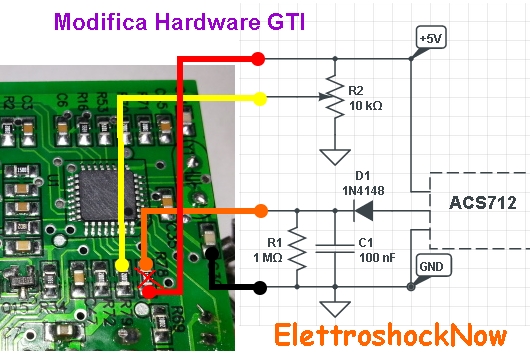
La resistenza R78 vŕ rimossa e vanno aggiunti i componenti come da schema.
Un esempio :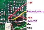
E' chiaro che il sensore amperometrico vŕ messo in serie all'utilizzatore o alla linea da tenere monitorata
La procedura per l'aggiornamento firmware rimane invariata con l'aggiunta delle seguenti impostazioni :
-Soglia Attivazione (Da 3 in su ,con valore proporzionato alla corrente dipendente dal tipo di sensore)
-Tempo Attivazione (espresso in secondi )
-Soglia Disattivazione (Da 3 in su )
-Taratura Offset Manuale (non necessario, ma utile per visualizzare il valore della taratura automatica)
-Configurazione GTI (per ora solo 3 configurazioni )
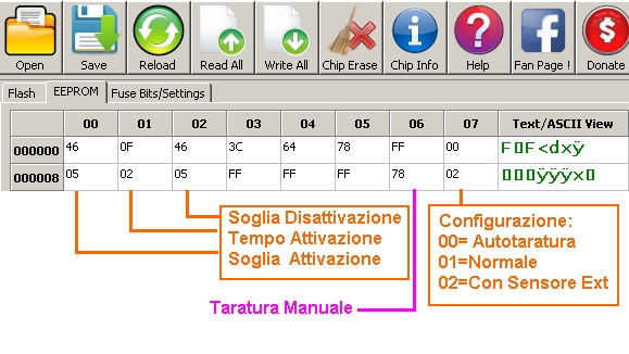
Procedura per configurare l'Offset del sensore automaticamente:
Per configurare l'Offset ,basterŕ caricare 0x00 nella configurazione GTI accertandosi che sia connesso ed alimentato il sensore l'ACS712 ,ma senza nessun carico (Da prove fatte posso confermare che il programmatore puň restare connesso all'inverter alimentato sia lato AC che DC con la possibilitŕ di aggiornare il firmware ,ma sopratutto variare i parametri della Eeprom senza disconnettere nulla .... E' chiaro che ad ogni aggiornamento avverrŕ un riavvio del sistema )
Caricato il nuovo firmware con impostato 0x00 l'inverter dopo l'automatico riavvio misurerŕ l'offset e lo memorizza nella Eeprom in posizione 0x0E (se si legge successivamente la memoria si puň vedere il valore sulla posizione Offset ) ed inoltre cambierŕ la configurazione GTI da 0x00 a 0x02 ,quindi l'inverter immetterŕ energia nella rete solo se si oltrepasseranno le soglie ...
Impostando 0x01 l'inverter immette sempre..... quindi disattivando il Sensore Amperometrico
E' chiaro che la funzione del potenziometro resta invariata in tutte le configurazioni ,e se non installato l'inverter immetterŕ il massimo impostato dalle soglie
Esempio soglie (puramente indicativi ):
Impostando 7 sia nella attivazione che nella disattiva ho rilevato l'immissione se il carico superava un assorbimento di 500mA (110W circa ) e si smettava di immettere se il carico assorbiva meno di 300mA
Impostando 10 = 1000mA / 800mA
impostando 15 = 1400mA /1150mA
ecc ecc ecc
Quindi si č liberi di scegliere le proprie preferenze ....
Ho aggiunto anche il tempo per evitare immissioni nei picchi di assorbimento rapidi ... quindi se ad esempio impostiamo 10 nel Time ,l'inverter immetterŕ solo se per dieci secondi continuativi l'assorbimento supera la soglia impostata.
Ciao e buon grid a tutti
ElettroshockNow
PS:Il codice Base in C QUI
/*
*****************************************************************************
**
** Project : GTI
**
** Component : GTI (ATmega8)
**
** Modulename : System
**
** Filename : GTI.c
**
** Abstract : This file is the implementation file for a grid tie
** inverter firmware
**
** Date : 2012-05-25
** Date mod : 2012-12-16 Modifications for Green power 350W, 14-28V inverter
**
*****************************************************************************
*/
/*
**===========================================================================
** 1 GENERAL
** 1.1 Revisions
**===========================================================================
*/
#define VERSION 100 //modifications by PetriK


/*
**===========================================================================
** 1.2 References
**===========================================================================
*/
// Hardware
// -------------- MCU LIB CONFIGURATION
#define FOSC (16000) // 16 MHz external crystal
#define F_CPU (FOSC*1000) // needed for AVR GCC


/*
**===========================================================================
** 1.3 Global user settings
**===========================================================================
*/
// define hardware
#define PJ14V // 14-28V nicht getestet!!!
//#define PJ28V // 28-52V

//#define _USE_LCD // LCD via HC164 serial shift register
//#define _DUMPLOAD // wenn Dumpload anschliessbar
#define _USE_BATTERY // if defined, disable MPPT and just seek for highest power


// define software (features)
//#define _PURESINE // exakte Sinustabelle
#define _MPPDELAY 30 // MPPTracker alle x*10ms
#define _MPPPOWERDIFF 4 // Leistungsdifferenz
#define _MPPMAXSTEP 15 // maximale Stepweite

/*
**===========================================================================
** 2. INCLUDE FILES
** 2.1 Standard include files
**===========================================================================
*/
#include <avr/io.h>
#include <avr/wdt.h>
#include <avr/interrupt.h>
#include <avr/pgmspace.h>

#include <util/delay.h> // benötigt F_CPU !!!

#include <string.h>
#include <stdint.h>


/*
**===========================================================================
** 2.2 Application include files
**===========================================================================
*/


/*
**===========================================================================
** 3. DECLARATIONS
** 3.1 Internal constants
**===========================================================================
*/
//PowerJack GTI 300 und 600
//Pinbeschreibung ATmega8:

// PortB
#define PWMDISABLE 0
#define PWMOUT 1
#define FANCONTROL 2 // 1 = EIN, 0 = AUS
#define _MOSI 3 // Daten/RS für LCD
#define _E 4 // Enable für LCD
#define _SCK 5 // CLK für LCD

// PortC
#define ADCUE 0 // Eingangsspannung Teiler 20:1
#define ADCIE 1 // Eingsngsstrom (150mV / A)
#define ADCUAC 2 // Netz-Sinus 4.5Vpp, ref 2.5V
#define ADCTEMP 3 // Temperaturmessung
#define DUMPLOAD 5 // 1 = AUS

// PortD 1 = EIN, 0 = AUS
#define RELAIS 1 // Eingangsrelais
#define LED3 2 // grün, Power
#define LED2 3 // grün, MPPTracker +
#define LED4 4 // grün, MPPTracker -
#define LED1 5 // rot, Fehler
#define ACCAPTURE 6 // Netz Sinus Vss 4.5V
#define ACREF 7 // +2.5V


// FuseBits1 = [CKOPT];
// FuseBits0 = [SUT1, BODLEVEL, BODEN];
// ProgMode = SPI;


// Temperatur: je höher der Wert desto höher die Temperatur
// entsteht aus 1023 - ADWert
#define _TempFanOn 680 //
#define _TempFanOff 660 //
#define _TempMax 850 // Übertemperatur


#ifdef PJ14V // Green Power 350W, 14-28V
//Spannungsgrenzen -> Spannungen nachfolgend in Zehntel Volt eintragen
#define _CurrMax 1000 // maximal zulässiger Strom ca.10 Ampere, modified by PetriK
#define _PeMax 2000 // maximale Eingangsleistung ca.200.0W, modified by PetriK

// Schaltschwellen für Eingang Relais
#define _UeRelOn 200 // ??? Relais ein 20V
#define _UeRelOff 170 // ??? Relais aus 17.5V

#define _UePwmOn 180 // Inverter startet 18V, modified by PetriK
#define _UePwmOff 175 // Inverter stopt 17.5V, modified by PetriK

#define _UeDumpLoadOn 300 // Dumpload zuschalten
#define _UeDumpLoadOff 280
#define _IeMin 2

#define _MUXUE 0x40 // ??
#define _MUXIE 0x41 // ??
#define _MUXUGRID 0x42 // ??
#define _MUXTEMP 0x43 // ??

#define _SCALE_UE 120 // Input voltage scaling; R1=2K, R2=18K = 100mV/V of input voltage, modified by PetriK
#define _SCALE_IE 1000 // Input current scaling; R30=18K, R26=27K = 120mV/A of input current as voltage, modified by PetriK
#define _SCALE_UG 200 // Grid voltage scaling; ?? Not sure what is the input pin for this and dont have test equipment - 200 seems to be working

#else
#ifdef PJ28V // PowerJack 28-52V
//Spannungsgrenzen -> Spannungen nachfolgend in Zehntel Volt eintragen
#define _CurrMax 900 // maximal zulässiger Strom ca.9A
#define _PeMax 3000 // maximale Eingangsleistung ca.3000W

// Schaltschwellen für Eingang Relais (1V =~ 11 AD-digits)
#define _UeRelOn 200 // Relais ein
#define _UeRelOff 180 // Relais aus

#define _UePwmOn 240 // Inverter startet ~24V
#define _UePwmOff 200 // Inverter stopt ~20V

#define _UeDumpLoadOn 540 // Dumpload zuschalten
#define _UeDumpLoadOff 520
#define _IeMin 2

#define _MUXUE 0x00
#define _MUXIE 0x01
#define _MUXUGRID 0x02
#define _MUXTEMP 0x03

#define _SCALE_UE 227 // 227/256=0.89
#define _SCALE_IE 530 // 530/256=2.07
#define _SCALE_UG 200 // 200/256=0.78

#else
#error 'please define a GTI type'
#endif
#endif


/*
**===========================================================================
** 3.2 Internal macros
**===========================================================================
*/
#define LED1_ON (PORTD|=(1<<led1))
#define LED2_ON (PORTD|=(1<<led2))
#define LED3_ON (PORTD|=(1<<led3))
#define LED4_ON (PORTD|=(1<<led4))
#define LED1_OFF (PORTD&=~(1<<led1))
#define LED2_OFF (PORTD&=~(1<<led2))
#define LED3_OFF (PORTD&=~(1<<led3))
#define LED4_OFF (PORTD&=~(1<<led4))

#define FAN_ON (PORTB|=(1<<fancontrol))
#define FAN_OFF (PORTB&=~(1<<fancontrol))

#define DUMPLOAD_ON (PORTC|=(1<<dumpload))
#define DUMPLOAD_OFF (PORTC&=~(1<<dumpload))

// für LCD (via HC164)
// SCK an HC164 Pin 8
// E an HC164 Pin 8
// MOSI an HC164 Pin 1 + 2 und LCD RS
// LCD R/W an Vss
// HC164 Qa..Qh an LCD D0..D7
// HC164 CLR (Pin 9) an VCC (+5V)
#define SCK_HIGH (PORTB|=(1<<_SCK))
#define E_HIGH (PORTB|=(1<<_E))
#define MOSI_HIGH (PORTB|=(1<<_MOSI))
#define SCK_LOW (PORTB&=~(1<<_SCK))
#define E_LOW (PORTB&=~(1<<_E))
#define MOSI_LOW (PORTB&=~(1<<_MOSI))


/*
**===========================================================================
** 3.3 Internal type definitions
**===========================================================================
*/
typedef struct
{
 uint8_t MppUp :1;
 uint8_t GridConnected :1;
 uint8_t OverTemp :1;
 uint8_t FanOn :1;
 uint8_t DumpOn :1;
 uint8_t T100ms :1;
 uint8_t Dummy1 :1;
 uint8_t Dummy2 :1;
} tdef_STATUS;


/*
**===========================================================================
** 3.4 Global variables (declared as 'extern' in some header file)
**===========================================================================
*/


/*
**===========================================================================
** 3.5 Internal function prototypes (defined in Section 5)
**===========================================================================
*/
void PortsInit( void );
void AdcInit( void );
void ACompInit( void );
void Timer1Init( void );
void Timer2Init( void );

void CheckUE( void );
void CheckUGrid( void );
void CheckTemp( void );

void SetDumpload( void );
void MPPTracker( void );

void WDT_On( uint8_t );
void WDT_Off( void );

void LCD_Init( void );
void LCD_Cmd( uint8_t );
void LCD_Data( uint8_t );

void PrintVal(uint16_t, uint8_t, uint8_t);
void LCD_PrintVal(uint8_t, uint8_t, uint16_t, uint8_t, uint8_t);
void LCD_PrintStr(uint8_t, uint8_t, int8_t *);

void wait( uint16_t );

uint16_t FSQRT( uint32_t);


/*
**===========================================================================
** 3.6 Internal variables
**===========================================================================
*/
// 'Sinustabelle' zur Modulation der Pulsbreite
#ifdef _PURESINE
const uint8_t Sine[100] = { 0, 0, 0, 0, 0, 0, 0, 0, 0, 0,
10, 20, 30, 40, 50, 60, 70, 80, 89, 99,
108, 117, 126, 135, 143, 152, 160, 167, 175, 182,
189, 196, 202, 208, 214, 219, 224, 229, 233, 237,
240, 243, 246, 249, 251, 252, 253, 254, 255, 255,
255, 255, 254, 253, 252, 251, 249, 246, 243, 240,
237, 233, 229, 224, 219, 214, 208, 202, 196, 189,
182, 175, 167, 160, 152, 143, 135, 126, 117, 108,
99, 89, 80, 70, 60, 50, 40, 30, 20, 10,
 0, 0, 0, 0, 0, 0, 0, 0, 0, 0 };
#else
const uint8_t Sine[100] = { 0, 0, 0, 0, 0, 0, 0, 0, 0, 0,
 5, 10, 20, 30, 40, 50, 60, 70, 79, 89,
 98, 107, 116, 125, 133, 142, 150, 157, 165, 172,
 179, 186, 192, 198, 204, 209, 214, 219, 223, 227,
 230, 233, 236, 239, 242, 245, 247, 249, 251, 252,
 255, 255, 254, 253, 252, 251, 249, 246, 243, 240,
 237, 233, 229, 224, 219, 214, 208, 202, 196, 189,
 182, 175, 167, 160, 152, 143, 135, 126, 117, 108,
 99, 89, 80, 70, 60, 50, 40, 30, 20, 10,
 0, 0, 0, 0, 0, 0, 0, 0, 0, 0 };
#endif

volatile tdef_STATUS Status;

volatile uint8_t SinePhase; // Zähler für StateMachine zur Ansteuerung UCC3806
volatile uint8_t FGridCnt;

volatile uint8_t RelCnt;

volatile uint16_t Ue;
volatile uint16_t UGrid;
volatile uint16_t Uac;
volatile uint16_t Ie;
volatile uint16_t Temp;
volatile uint16_t FGrid;
volatile uint16_t Power;
volatile uint16_t LastPower;

volatile uint16_t PulseWidth;

#ifdef _USE_LCD
static const uint8_t LCDline[3] = {0, 0x80-1, 0xC0-1};
static int8_t Printstring[16];
#endif


/*
**===========================================================================
** 4. GLOBAL FUNCTIONS (declared as 'extern' in some header file)
**===========================================================================
*/
///////////////////////////////////////////////////////////////////////////////
// Hauptprogramm
int16_t main( void )
{
 static uint8_t disp = 0;

 cli(); // clear Global Interrupt Enable

 wdt_reset();
 WDT_On(WDTO_250MS);

 PortsInit();
 AdcInit();
 ACompInit();
 Timer1Init();
 Timer2Init();

 LED1_ON;
 LED2_ON;
 LED3_ON;
 LED4_ON;
 wait(20000);
 LED1_OFF;
 LED2_OFF;
 LED3_OFF;
 LED4_OFF;

 WDT_On(WDTO_250MS);
#ifdef _USE_LCD
 LCD_Init();
#endif
 WDT_On(WDTO_250MS);
 sei(); // set Global Interrupt Enable

 for(;<img src='faccine/wink.gif' alt="faccine/wink.gif" style="max-width:700px;max-height:1700px;"/> // loop ca 5us
 {
 if( Status.T100ms ) // alle 100ms
 {
 wdt_reset();
 Status.T100ms = 0;

 #ifdef _USE_LCD
 if( disp>=3 )
 {
 LCD_Cmd(0x80);
 LCD_Data(' ');
 LCD_Data(' ');
 LCD_Data(' ');
 LCD_Data(' ');
 LCD_Data(' ');
 LCD_Data(' ');
 LCD_Data('V');
 LCD_Data(' ');
 LCD_Data(' ');
 LCD_Data(' ');
 LCD_Data(' ');
 LCD_Data(' ');
 LCD_Data(' ');
 LCD_Data(' ');
 LCD_Data('A');
 LCD_Data(' ');
 LCD_PrintVal(1, 3, Ue, 3, 1);
 LCD_PrintVal(1, 10, Ie, 4, 2);
 LCD_Cmd(0xC0);
 if( Status.OverTemp )
 LCD_Data('T');
 else
 LCD_Data(' ');
 LCD_Data(' ');
 LCD_Data(' ');
 LCD_Data(' ');
 LCD_Data(' ');
 LCD_Data(' ');
 LCD_Data('W');
 LCD_Data(' ');
 LCD_Data(' ');
 LCD_Data(' ');
 LCD_Data(' ');
 LCD_Data(' ');
 LCD_Data(' ');
 LCD_Data(' ');
 LCD_Data('V');
 LCD_Data(' ');
 LCD_PrintVal(2, 2, Power, 4, 1);
 LCD_PrintVal(2, 12, UGrid, 3, 0);
 disp = 0;
 }
 else
 disp++;
 #endif
 }
 }
}


/*
**===========================================================================
** 5. INTERNAL FUNCTIONS (declared in Section 3.5)
**===========================================================================
*/
void PortsInit( void )
{
 PORTB = 0x21; //
 DDRB = (1<<pwmdisable)|(1<<pwmout)|(1<<fancontrol)|(1<<_MOSI)|(1<<_E)|(1<<_SCK);

 PORTC = 0x00; // ADC0-4, DumpLoad
 DDRC = (1<<dumpload);

 PORTD = 0x00; // pd0 Relais, pd2,5 Leds0..3 , PD6,7 Analog Comparator
 DDRD = 0x3F;
// DDRD = (1<<relais)|(1<<led1)|(1<<led2)|(1<<led3)|(1<<led4);
}


void AdcInit( void )
{
 ADCSRA = (1<<aden)|(1<<adps2)|(1<<adps1); // Vorteiler 64
 ADMUX = _MUXUE; // REFS1,REFS0 = Vref 5V
 ADCSRA |= (1<<adsc); // start conversion
}


void ACompInit( void )
{
 ACSR = (1<<acie); // enable analog comparator Interrupt
}


ISR(ANA_COMP_vect)
{
 ACSR = 0; // disable Interrupt um Storungen zu unterdrücken
 SinePhase = 0;
 if( FGridCnt<5 )
 FGridCnt++;
 // initialisiere Timer2
 TCNT2 = 0;
 TCCR2 = (1<<wgm21)|(1<<cs21); // CTC operation, Prescaler 8
 TIFR |= (1<<ocf2); // lösche Interrupt
 TIMSK |= (1<<ocie2); // enable Interrupt TOIE2;
}


void Timer1Init( void )
{
 OCR1A = 0;
 TCCR1A = (0<<wgm10)|(1<<wgm11)|(1<<com1a1);
 TCCR1B = (1<<wgm12)|(1<<cs10);
}


void Timer2Init( void )
{
 TCCR2 = 0; // disable counter
 TCNT2 = 0; // clear counter
 OCR2 = 200; // 200*500ns = 100us
 TCCR2 = (1<<wgm21)|(1<<cs21); // CTC operation, OCR2 Top, Prescaler 8
 TIFR |= (1<<ocf2); // lösche Interrupt
 TIMSK |= (1<<ocie2); // enable Interrupt TOIE2;
}


ISR(TIMER2_COMP_vect) // jede 100us
{
 uint16_t tmp;
 static uint32_t tmpL;
 static uint8_t T1sCnt = 0;
 static uint16_t T100msCnt = 0;
 static uint8_t UgCnt = 0;
 static uint32_t UgSum = 0;
 static uint16_t UeSum = 0;
 static uint8_t UeCnt = 0;
 static uint16_t IeSum = 0;
 static uint8_t IeCnt = 0;


 uint16_t ADCval;

 if( (ADCSRA&(1<<adsc))==0 ) // ADC fertig? (sollte immer der Fall sein)
 {
 ADCval = ADCW; // lese ADC ein
 switch( ADMUX )
 {
 case _MUXUE: // letzte Messung war Ue
 ADMUX = _MUXIE; // nächste Messung Ie
 ADCSRA |= (1<<adsc); // ADC starten
 if( UeCnt<64 )
 {
 UeSum += ADCval; // Ue aufsummieren
 UeCnt++;
 }
 break;
 case _MUXIE: // letzte Messung war Ie
 ADMUX = _MUXUGRID; // nächste Messung Unetz
 ADCSRA |= (1<<adsc); // ADC starten
 if( IeCnt<64 )
 {
 IeSum += ADCval; // Ie aufsummieren
 IeCnt++;
 }
 break;
 case _MUXUGRID: // letzte Messung war Ugrid
 ADMUX = _MUXTEMP; // nächste Messung Temp
 ADCSRA |= (1<<adsc); // ADC starten
 if( UgCnt<64 )
 { // TRMS Messung Unetz
 if( ADCval>512)
 ADCval = ADCval-512;
 else
 ADCval = 512-ADCval;
 UgSum += (uint32_t)ADCval*ADCval; // Quadrate aufsummieren
 UgCnt++;
 }
 else // nach ~26ms ohne Nulldurchgang
 {
 UgSum = 0; // Werte 'ungültig' machen
 UgCnt = 0;
 UGrid = 0;
 }
 break;
 case _MUXTEMP: // letzte Messung war Temp
 ADMUX = _MUXUE; // nächste Messung Ue
 ADCSRA |= (1<<adsc); // ADC starten
 ADCval = 1023-ADCval;
 Temp = (Temp+Temp+Temp+ADCval+2)>>2; // filtere Temperatur
 break;
 default: // redundant!!!
 ADMUX = _MUXUE; // nächste Messung Ue
 ADCSRA |= (1<<adsc); // ADC starten
 break;
 }
 }

 // schalte PWM nach 1ms für 8ms ein
 switch( SinePhase++ )
 {
 default:
 break;
 case 1: // TRMS Berechnung UGrid 1.Teil
 tmpL = (UgSum+(UgCnt/2))/UgCnt;
 UgSum = 0uL;
 UgCnt = 0;
 break;
 case 2: // TRMS Berechnung UGrid 2.Teil
 tmp = ((uint32_t)FSQRT(tmpL)*_SCALE_UG)>>8;
 UGrid = (UGrid+tmp+1)>>1; // Auflösung V
 break;
 case 3: // Berechnung und Filterung Ue
 tmp = (UeSum+(UeCnt/2))/UeCnt;
 tmp = ((uint32_t)tmp*_SCALE_UE)>>8;
 Ue = (Ue+tmp+1)>>1; // Auflösung 1/10V
 UeSum = 0;
 UeCnt = 0;
 break;
 case 4: // Berechnung und Filterung Ie
 tmp = (IeSum+(IeCnt/2))/IeCnt;
 tmp = ((uint32_t)tmp*_SCALE_IE)>>8;
 Ie = (Ie+tmp+1)>>1; // Auflösung 1/10A
 IeSum = 0;
 IeCnt = 0;
 break;
 case 5: // Leistung berechnen
 Power = ((uint32_t)Ue*Ie)/100; // Auflösung 1/10W
 Uac = (Uac+Uac+Uac+UGrid+2)>>2; // filtere Uac für Anzeige
 break;
 case 6: // MPP-Tracker
 MPPTracker();
 break;
 case 7: // Netzspannung überwachen
 CheckUGrid();
 break;
 case 8: // Eingangsspannung überwachen
 CheckUE();
 break;
 case 10: // ~1ms nach Nulldurchgang
 break;
 case 52: // ~6ms nach Nulldurchgang
 ACSR = (1<<aci);
 ACSR = (1<<acie); // enable analog comparator Interrupt
 break;
 case 90: // ~9ms nach Nulldurchgang
 break;
 case 110: // 11ms nach Nulldurchgang
 if( FGridCnt ) // NetzOK Zähler reduzieren
 FGridCnt--;
 break;
 case 220: // und 22ms nach Nulldurchgang
 if( FGridCnt ) // NetzOK Zähler reduzieren
 FGridCnt--;
 break;
 }


 if( !(PORTB&(1<<pwmdisable))&&(SinePhase>=10)&&(SinePhase<=90) )
 OCR1A = (uint32_t)PulseWidth*Sine[SinePhase]>>8;
 else
 OCR1A = 0; // PWM ausschalten


 if( T100msCnt>=1000 ) // alle 100ms
 {
 T100msCnt = 0;

 Status.T100ms = 1;
 if( T1sCnt>=10 ) // jede Sekunde
 {
 T1sCnt = 0;
 if( (Ue<_UePwmOff)||(!Status.GridConnected)||(Status.OverTemp) )
 LED1_ON; // Fehler-LED EIN
 else
 LED1_OFF; // Fehler-LED AUS

 CheckTemp(); // Temperaturüberwachung
 }
 else
 T1sCnt++;
 }
 else
 T100msCnt++;

}


void CheckUE( void )
{
 if( (Ue<_UePwmOff)||(!Status.GridConnected)||(Status.OverTemp) )
 {
 OCR1A = 0;
 PORTB |= (1<<pwmdisable);
 PulseWidth = 0;
 LastPower = 0;
 LED2_OFF;
 LED3_OFF;
 LED4_OFF;
 }
 else if( (Ue>_UePwmOn)&&(Status.GridConnected)&&(Temp<_TempMax) )
 {
 if( PORTB&(1<<pwmdisable) )
 {
 LED4_ON;
 Status.MppUp = 1;
 LastPower = 0;
 PulseWidth = 5;
 PORTB &= ~(1<<pwmdisable);
 }
 }
 else
 {}
#ifdef _DUMPLOAD
 SetDumpload();
#endif
}


// Prüft, ob Netzspannung anliegt
void CheckUGrid( void )
{
 if( (UGrid>200)&&(FGridCnt>=4) )
 Status.GridConnected = 1;
 else
 Status.GridConnected = 0;
}


// Prüft die Temperatur und schaltet ggf. Lüfter aus/ein
void CheckTemp( void )
{
 if( (Temp>_TempFanOn) )
 {
 Status.FanOn = 1; // Lüfter ein
 FAN_ON;
 if( Temp>_TempMax )
 Status.OverTemp = 1;
 else
 Status.OverTemp = 0;
 }
 else if( Temp<_TempFanOff )
 {
 Status.FanOn = 0; // Lüfter aus
 FAN_OFF;
 }
 else
 {}
}

#ifdef _USE_BATTERY
//
// MPPTracker modfified for battery use, i.e. always max power, not seeking best power point. Use this for battery power to GTI
//
void MPPTracker( void )
{
 static uint8_t StepSize = 5;
 static uint8_t MpptCnt = 0;

 if( ++MpptCnt>=_MPPDELAY )
 {
 MpptCnt = 0;

 if( (Ue<_UePwmOn)||(Ie>_CurrMax)||(Power>_PeMax) ) // bei diesen Fehlern
 {
 Status.MppUp = 0; // Suchrichtung niedrigerer Strom
 }
 else
 {
 Status.MppUp = 1;
 }

 LastPower = Power;

 if( Status.MppUp ) // Suchrichtung höherer Strom
 {
 if( PulseWidth<(512-_MPPMAXSTEP) )
 PulseWidth += StepSize;
 LED2_OFF;
 LED3_ON;
 }
 else // Suchrichtung niedrigerer Strom
 {
 if( PulseWidth>(_MPPMAXSTEP+2) )
 PulseWidth -= StepSize;
 LED2_ON;
 LED3_OFF;
 }

 }
}

#else
//
// Original MPPTracker seeking for best power point, use for solar PV only. With a battery this creates load peaks.
//
void MPPTracker( void )
{
 static uint8_t StepSize = 1;
 static uint8_t MpptCnt = 0;

 if( ++MpptCnt>=_MPPDELAY )
 {
 MpptCnt = 0;

 if( (Ue<_UePwmOn)||(Ie>_CurrMax)||(Power>_PeMax) ) // bei diesen Fehlern
 {
 Status.MppUp = 0; // Suchrichtung niedrigerer Strom
 }
 else if( Power<(LastPower+_MPPPOWERDIFF) ) // wenn die Leistung nicht ansteigt
 { // dann kehre die Suchrichtung um
 StepSize = 1;
 if( Status.MppUp )
 Status.MppUp = 0;
 else
 Status.MppUp = 1;
 }
 else // wenn die Leistung steigt
 {
 if( StepSize<_MPPMAXSTEP ) // Schrittweite erhöhen
 StepSize++;
 }

 LastPower = Power;

 if( Status.MppUp ) // Suchrichtung höherer Strom
 {
 if( PulseWidth<(512-_MPPMAXSTEP) )
 PulseWidth += StepSize;
 LED2_OFF;
 LED3_ON;
 }
 else // Suchrichtung niedrigerer Strom
 {
 if( PulseWidth>(_MPPMAXSTEP+2) )
 PulseWidth -= StepSize;
 LED2_ON;
 LED3_OFF;
 }

 }
}
#endif

#ifdef _DUMPLOAD
void SetDumpload( void )
{
 // Ue ist größer als Einschaltschwelle
 if( (Ue>_UeDumpLoadOn)||(Status.GridConnected==0) )
 {
 DUMPLOAD_ON;
 Status.DumpOn = 1;
 }
 else if( Ue<_UeDumpLoadOff )
 {
 DUMPLOAD_OFF;
 Status.DumpOn = 0;
 }
 else
 {}
}
#endif


void WDT_On(uint8_t WDtimeout) // Watch-Dog On
{
 WDTCR = (1<<wdce) | (1<<wde); // WD Change enable
 WDTCR = WDtimeout; // set WD to timeout periode
}


void WDT_Off(void) // Watch-Dog Off
{
 WDTCR = (1<<wdce) | (1<<wde); // WD Change enable
 WDTCR = 0x00; // WD disable (off), Turn off WDT
}


uint16_t FSQRT(uint32_t Quadrat) // Dauer: ~600-800 cycles
{
 uint16_t Wurzel = 0; // Startwert Wurzel
 uint16_t tmp = 512; // Korrekturwert (Intervallhalbierung)

 while(tmp)
 {
 if( ((uint32_t)(Wurzel+tmp) * (Wurzel+tmp)) <= Quadrat )
 Wurzel+=tmp;
 tmp=tmp>>1; // /2
 }

 return (Wurzel); // Wurzel zurückgeben
}


void wait( uint16_t val )
{
 volatile uint16_t tmp = val;

 while(tmp--);
}


#ifdef _USE_LCD
void LCD_Cmd( uint8_t Wert )
{
 uint8_t maske = 0x80;

 while( maske )
 {
 if( Wert&maske )
 MOSI_HIGH;
 else
 MOSI_LOW;
 SCK_HIGH;
 SCK_LOW;
 maske = maske>>1;
 }
 MOSI_LOW; // RS = 0
 E_HIGH;
 E_LOW;
 wait(800);
}


void LCD_Data( uint8_t Wert )
{
 uint8_t maske = 0x80;

 while( maske )
 {
 if( Wert&maske )
 MOSI_HIGH;
 else
 MOSI_LOW;
 SCK_HIGH;
 SCK_LOW;
 maske = maske>>1;
 }
 MOSI_HIGH; // RS = 1
 E_HIGH;
 E_LOW;
 wait(800);
}


void LCD_Init( void )
{
 SCK_LOW;
 MOSI_LOW;
 E_LOW;

 wait(6000);
 LCD_Cmd(0x38);
 wait(600);
 LCD_Cmd(0x38);
 wait(600);
 LCD_Cmd(0x38);
 wait(600);
 LCD_Cmd(0x0c);
 wait(600);
 LCD_Cmd(0x01);
 wait(6000);
 LCD_Cmd(0x06);
 wait(600);
}


void PrintVal(uint16_t Val, uint8_t Digits, uint8_t Comma )
{ uint8_t n, tmp;

 if (Comma) // decimal point to be printed?
 {
 Comma=(Digits-Comma);
 if (Comma) //
 {
 Digits++; // add one digit for '.'
 }
 else
 {
 Comma = 10; // print leading zeros (e.g. 007)
 }
 }
 tmp = (Digits-1);
 Printstring[Digits]=0; // null-terminate string in advance
 while (Digits--) // solange Zahlen zum Darstellen
 {
 if(Comma || Val) // if something is left for printing
 {
 n = (Val%10)+Ɔ'
 }
 else
 {
 n = ' ' // leading spaces
 }
 if (Comma)
 {
 if (Digits==Comma)
 {
 Printstring[Digits]='.'
 Digits--;
 Comma = 0;
 }
 }
 Val = Val/10;
 Printstring[Digits]=n;
 }
 if(Printstring[tmp]== ' ')
 {
 Printstring[tmp] = Ɔ'
 }
} // PrintVal


void LCD_PrintVal(uint8_t y, uint8_t x, uint16_t Val,
 uint8_t Digits, uint8_t Colon)
{
 PrintVal(Val, Digits, Colon);
 LCD_PrintStr(y, x, Printstring); // 'Printstring[8]' set in PrintVal()
}


void LCD_PrintStr(uint8_t y, uint8_t x, int8_t *ucStr)
{
 uint8_t i=0;

 LCD_Cmd((uint8_t)(LCDline[y]+x));
 while ((ucStr[i]!=0) && (i<=16))
 {
 LCD_Data((uint8_t)ucStr[i]);
 i++;
 }
}
#endif

/*
**===========================================================================
** END OF FILE
**===========================================================================
*/
Firmware_GT_con_Limitatore_Eeprom_Sensore_Amperometrico.hex
|